Introduction
Chain Home Transmitters and Receivers
On 24th September 1937, RAF Bawdsey located near Felixstowe, Suffolk, became the first fully operational Radar station
in the world. Remarkably, this was only eighteen months after the first experiment, conducted by Robert Watson Watt and
Arnold Wilkins, which established that by using transmitted radio waves it was possible to detect an approaching aircraft.

The experimental 240ft (73m) wooden receiver towers and 360ft (109m) steel transmitter towers were built and Bawdsey became the first Chain Home Radar Station. By the outbreak of World War II a chain of radar stations was in place around the coast of Britain,
Chain Home Type 1 came in two versions, either East Coast or West Coast, east Coast sites used three or four 360ft (109m) steel lattice towers for transmission
and west coast sites used 360 ft guyed masts rather than towers for supporting the aerial. RAF Bawdsey and Worth were unique in that they had Coast Defence
(CD), Chain Home Low (CHL) and Chain Home (CH) equipment together on one site. Worth was a West Coast version with receiver aerials, on
two wooden 240ft (75metre) masts placed on A site and the transmitter’s 360 ft guyed masts were positioned 600 metres south 15. (Select thumbnail image for Worth map)
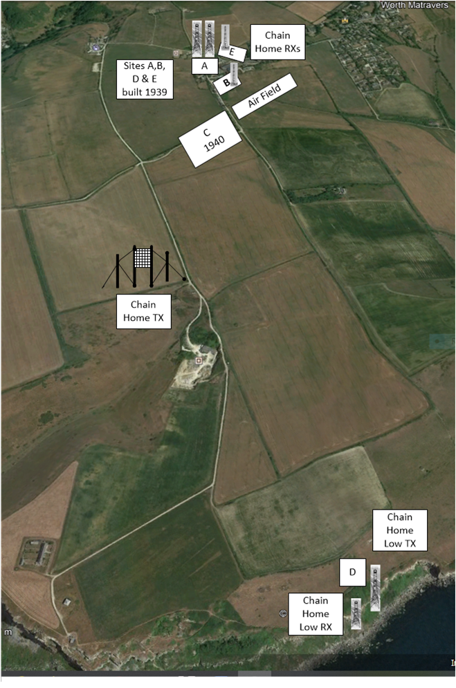
More usually, stations only operated a CH or a CHL system, here a CH station acted as the parent station for those operating the CHL role. The full names of the systems were Chain Station
Home Service and Chain Station Home Service
– Low Cover, for the detection of low altitude 500 ft (152m) aircraft, were operated at about 200 MHz – wavelength at about one and a half metres. This high frequency was required because to see targets above the sea is proportional to the ratio between operational wavelength and the height of the aerial above the sea.
Between two transmitter towers the main aerial array was attached to the top and ground near the bottom of each tower,
then 12 aerials, known as a half wave Dipole, were spaced verticallly 18 feet apart. From the length of the half-wave dipole
it's straight forward to work out what frequency was used. Since half a wavelength was 18 ft (5.5m), the wavelength was 11m, which corresponds
to a frequency of 27 MHz.
The Chain Home stations were designed to operate at 20–50 MHz, the "boundary area" between high frequency and VHF bands at 30 MHz, although
typical operations were at 20–30 MHz (the upper end of the HF band), or about a 12 m wavelength. The availability of multiple operating
frequencies gave some protection from jamming. The detection range was typically 120 mi (190 km; 100 nmi), but could be better 15.
Today's mobile phones use frequencies a hundred times higher than this, but in the late 1930s it was not a simple matter to generate 250 kW at 30 MHz, nor to design a suitable receiver.
frequency (MHz)= 300 / wavelength (m).

To increase the transmission power another array was connected to an identical set of towers, providing a total of three arrays.
The task facing the designer of an aerial system is to arrange the structure so that as much as possible of the radiated
energy goes in the right direction. A simple horizontal dipole by itself won't do - it radiates in all directions
(except along its axis). The CH transmitter aerial array included a curtain of reflectors hung on the landward side to redirect
this energy outwards, across the sea, to where it was useful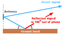 4.
4.
The main problem in controlling the azimuth of the radiation (that is, the angle from the horizontal) is that the ground
acts as a mirror, so it's practically impossible to send the energy out horizontally. The best solution is to keep the ground
as far away as possible.
Although, some energy is always reflected from the ground and unfortunately the reflection process adds 180 degrees of phase shift.
This means that at some angle the reflected signal and the direct signal will cancel each other out and no energy is transmitted.
The performance of an aerial is usually illustrated by means of its polar diagram, 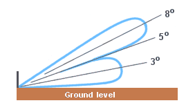 which shows how much energy (in relative terms) is radiated in each direction. The performance of the CH transmitter aerials looked something like
the diagram on the right, with zero power at about 5 degrees above the horizontal. With almost no energy being transmitted at 5 degrees, the system was effectively blind in this direction.
The blind spot was removed by adding a supplementary array, known as the gap filler, suspended underneath the main array. Its polar diagram was designed to radiate maximum energy at 5 degrees.
At 360 feet tall, the Chain Home transmitter towers were huge - just about the same height as St. Paul's Cathedral.
This allowed their aerials to send 5-45 micro second pulses repeated every 12.5, 25 or 50 second 5 to enemy aircraft flying at 1,000 feet when they were still 40 miles away and if the enemy aircraft flew at 15,000 feet, they could be seen 150 miles away. The transmitter array acted as a floodlight - it broadcast energy out to sea over a wide angle. This meant that a station had to be built every 20 miles or so along the coast, to give continuous overlapping coverage.
It also meant that the receiving aerials had to be quite sophisticated. A simple dipole aerial would detect the echo returning from an aircraft,
but would give no sense of whereabouts of the aircraft.
4
which shows how much energy (in relative terms) is radiated in each direction. The performance of the CH transmitter aerials looked something like
the diagram on the right, with zero power at about 5 degrees above the horizontal. With almost no energy being transmitted at 5 degrees, the system was effectively blind in this direction.
The blind spot was removed by adding a supplementary array, known as the gap filler, suspended underneath the main array. Its polar diagram was designed to radiate maximum energy at 5 degrees.
At 360 feet tall, the Chain Home transmitter towers were huge - just about the same height as St. Paul's Cathedral.
This allowed their aerials to send 5-45 micro second pulses repeated every 12.5, 25 or 50 second 5 to enemy aircraft flying at 1,000 feet when they were still 40 miles away and if the enemy aircraft flew at 15,000 feet, they could be seen 150 miles away. The transmitter array acted as a floodlight - it broadcast energy out to sea over a wide angle. This meant that a station had to be built every 20 miles or so along the coast, to give continuous overlapping coverage.
It also meant that the receiving aerials had to be quite sophisticated. A simple dipole aerial would detect the echo returning from an aircraft,
but would give no sense of whereabouts of the aircraft.
4
The receiving aerial towers were smaller and lighter, they were 240 feet high and built of wood.
The aerials were used in pairs, as shown in the top sidebar, to determine both the bearing of the target
aircraft and its height.
Royal Candian Air Force Aerial Training YouTube Video 1959.